

Structure and configuration of settings.ini
General
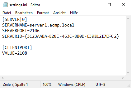
The settings.ini is a configuration file in which the initialisation of the data is stored. It is used so that the agents that have connected to the server can retrieve and check the details of the ACMP Clients. The file contains all the relevant information about the server (the name, port and server ID) by default, as well as the information about the client port that can be used to push the jobs from the server to the clients.
The settings.ini is located in the shared folder of the ACMP Server (C:\Program Files (x86)\Aagon\ACMP Server\Clients). Open the settings.ini with a common text editor to view the file content.
Content of a settings.ini
Structure of a settings.ini
The configuration file can contain either a single server entry or several server entries (see Use Case: Installing ACMP Gateway via MSI). This makes it possible to address several ACMP Servers directly within a single file, to create network mappings, to prepare server migrations or to create „multi-server clients“.
The information contained is always listed line by line, with an equal sign separating the key from its value:
SERVERPORT=2106
For a better overview, the keys are divided into groups called sections. To do this, the name of a file that is to be clearly defined must be enclosed in square brackets. The spelling of the key is not case-sensitive.
Example:
Key=Value
Key2=Value
[Section1]
Key=Value
Key2=Value
Schlüssel3=Wert
Please note that each section and each key used may only occur once per section. If you wish to store comments in the file, these must be preceded by a semicolon and placed on a separate row. Example:
SERVERNAME=server1.acmp.local
SERVERPORT=2106
; check the server name for information on whether the caption has changed
Example of a settings.ini
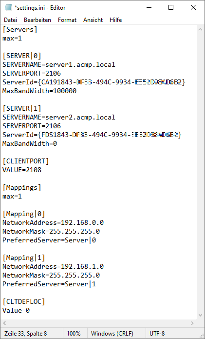
The example below shows a sample file containing the configuration of two server entries, the mapping and the installation path of the Client. The column Value indicates what can be entered in a settings.ini. The column Explanation explains and justifies the respective content.
| Value | Explanation | |
| 1. | [Servers] | Specifies the section, i.e. the [Servers] |
| 2. | max=1 | Indicates the value (max) and the indication of the available Servers. The content is 1, where counting starts at 0. |
| 3. | ||
| 4. | [SERVER|0] | Specifies the SERVER section and the first server; the count starts at 0 (zero). The syntax is therefore SERVER|<N> |
| 5. | SERVERNAME=server1.acmp.local | The content is the key (SERVERNAME) and the value (server1.acmp.local) separated by an equal sign; here the server name or the IP of the ACMP Server to be used. |
| 6. | SERVERPORT=2106 | The key (SERVERPORT) corresponds to the value of the ACMP server port to be used, in this example port 2106 |
| 7. | ServerId={CA191843-xxxx-494C-9934-xxxxxxxxxxxx} | The key (ServerId) has been assigned the value of the server ID ({CA191843-xxxx-494C-9934-xxxxxxxxxxxx}) |
| 8. | MaxBandWidth=100000 | MaxBandWidth stands for the maximum bandwidth to be used (bits per second). If the specification is unlimited, a zero can also be entered (0=unlimited). |
| 9. | ||
| 10. | [SERVER|1] | Recurrence of row 4, only for the second listed Server ([SERVER|1])) |
| 11. | SERVERNAME=server2.acmp.local | Recurrence of row 5 (Server name or the IP of the ACMP Server) |
| 12. | SERVERPORT=2106 | Recurrence of row 6 (specification of server port) |
| 13. | ServerId={FDS1843-xxxx-494C-9934-xxxxxxxxxxxx} | Recurrence of row 7 (specification of Server ID) |
| 14. | MaxBandWidth=0 | Recurrence of row 8 for maximum bandwidth in bits per second |
| 15. | ||
| 16. | [CLIENTPORT] | Specifies the section, in this case the [CLIENTPORT]. The port is used to push Jobs from the Server to the Clients. |
| 17. | VALUE=2108 | Indicates the value (VALUE) and the content of the ACMP client port used |
| 18. | ||
| 19. | [Mappings] | Introduces the [Mappings] section |
| 20. | max=1 | The value (max) indicates the number of available mappings, starting from 0 (zero). |
| 21. | ||
| 22. | [Mapping|0] | Introduces the mappings section. The first mapping must start with the number 0 (zero) (Mapping|<N>) |
| 23. | NetworkAddress=192.168.0.0 | The NetworkAddress key specifies the net address to which the mapping should apply. The value for this is written after the equals sign. |
| 24. | NetworkMask=255.255.255.0 | The NetworkMask key specifies the net mask to which the mapping should apply (here: 255.255.255.0) |
| 25. | PreferredServer=Server|0 | Specifies the server to be used (Server|0), which was previously named in row 4. |
| 26. | ||
| 27. | [Mapping|1] | Recurrence of row 22, where the second mapping is defined ([Mapping|1]) |
| 28. | NetworkAddress=192.168.1.0 | Recurrence of row 23 with the adapted net address for the mapping |
| 29. | NetworkMask=255.255.255.0 | Recurrence of row 24 with the net mask |
| 30. | PreferredServer=Server|1 | Recurrence of row 25 with the specification of the server to be used (Server|1), which was named in row 10 |
| 31. | ||
| 32. | [CLTDEFLOC] | The [CLTDEFLOC] section specifies the default storage location for the client. |
| 33. | Value=0 | The value determines where the installation path of the Clients should be: 0=C:\ACMPClient 1=1:\Program Files (x86)\ACMPClient |
Configured settings.ini
Procedure of the Clients
As soon as one or more mappings have been stored in a settings.ini, the specified servers are initially ignored. The client checks all the entered mappings and, for each individual mapping, checks whether the current IP address matches the information in the section. If the IP matches, the client enters the server that was stored under ‘PreferredServer’ in its server list. If no mapping matches, all servers are entered into the server list in sequence. If the client cannot reach the current server, it falls back to the next one on its list. For continuing server requests, the last accessible server is contacted first. When an agent is restarted, another attempt is made to reach the primary server.